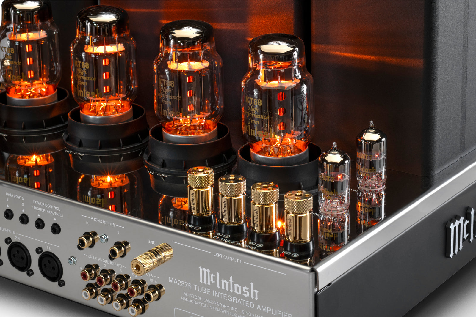
A founding McIntosh technology
The McIntosh Unity Coupled Circuit
McIntosh's Unity Coupled Circuit is a vacuum-tube output-stage design in which specially wound transformer sections participate in both the plate and cathode circuits. Emerging from the engineering work that led to the company's founding, the architecture addresses the bandwidth, distortion, and loudspeaker-matching compromises that had limited conventional high-power tube amplifiers.

The idea in 60 seconds
McIntosh changed the relationship between the tubes and the output transformer.
The music signal controls current
A small voltage at each tube's grid regulates a much larger current supplied by the amplifier's power supply.
The transformer meets the loudspeaker
The output transformer combines the push-pull waveform and matches the tubes' operating conditions to the loudspeaker.
Unity Coupling shares the work
Closely coupled windings in both the plate and cathode paths make the transformer part of the tubes' operating circuit.
Wide bandwidth, low distortion, controlled power transfer, and the amplifier's rated output at its designated loudspeaker connections.
See the relationship
The plate, cathode, transformer, and loudspeaker are one working system.
The red plate/anode path and white cathode path enter closely coupled transformer windings. On the isolated secondary side, white identifies common while two shades of red distinguish the 4- and 8-ohm positive taps.

Why it is a reason to choose McIntosh
The transformer is not an accessory to the circuit. It is central to the circuit.
The design is meaningful because the output transformer is not merely attached to a familiar tube circuit; it is part of the way the output tubes operate. Selectable loudspeaker taps—such as the 4- and 8-ohm connections—let the transformer present the tube output stage with the load it was designed to work into while matching that stage to the loudspeaker's impedance. The tubes therefore retain their intended operating relationship instead of being asked to drive different loudspeaker loads directly. This close match supports power transfer, low distortion, broad response, and consistent control of the loudspeaker.
Within the amplifier's operating limits, the goal is not to add a conspicuous tube effect. It is to preserve musical shape and timing with low distortion, extended bandwidth, and consistent control of the loudspeaker. The result McIntosh is pursuing is clarity without giving up the scale and physical presence for which a powerful tube amplifier is chosen.
The circuit made physical
Tubes, transformers, and dedicated loudspeaker connections.
The current MC275 provides a clear view of a living Unity Coupled design. Its two Unity Coupled output transformers sit beside the power transformer, while the chassis exposes the output tubes and dedicated 4-, 8-, and 16-ohm loudspeaker connections.
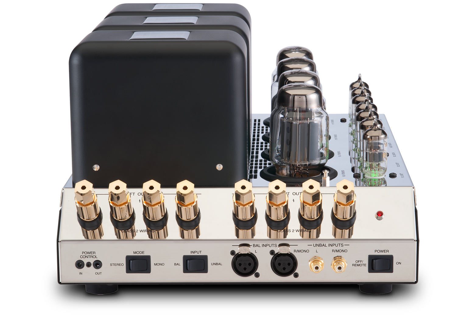
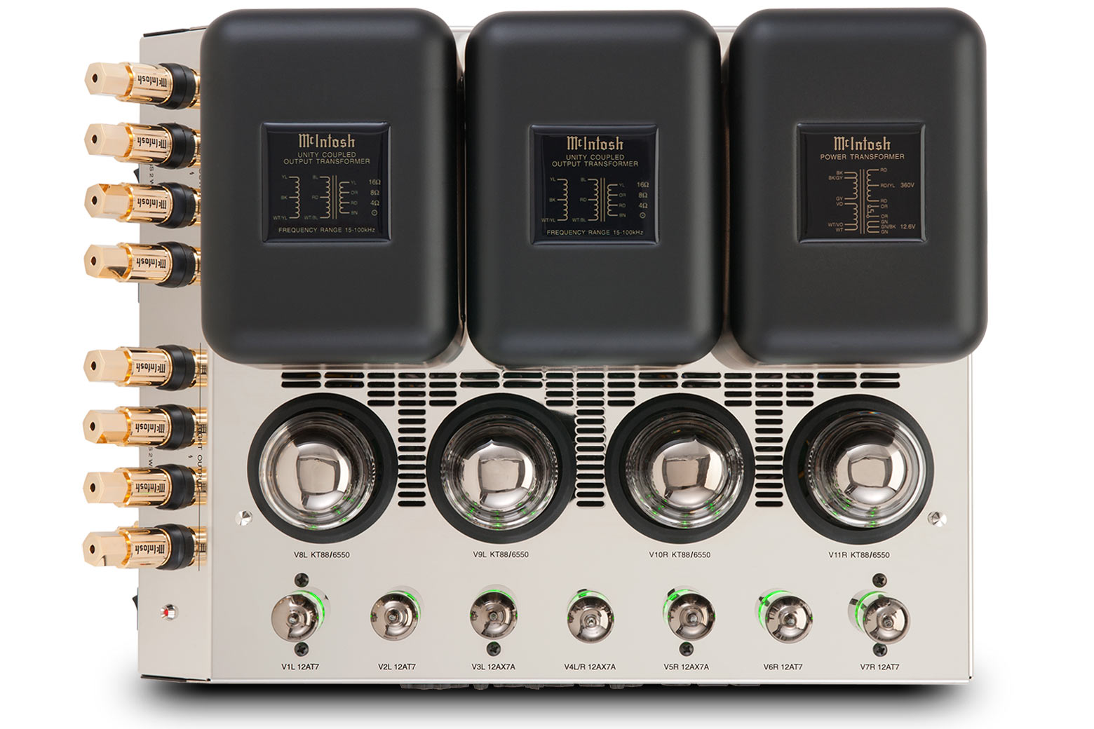
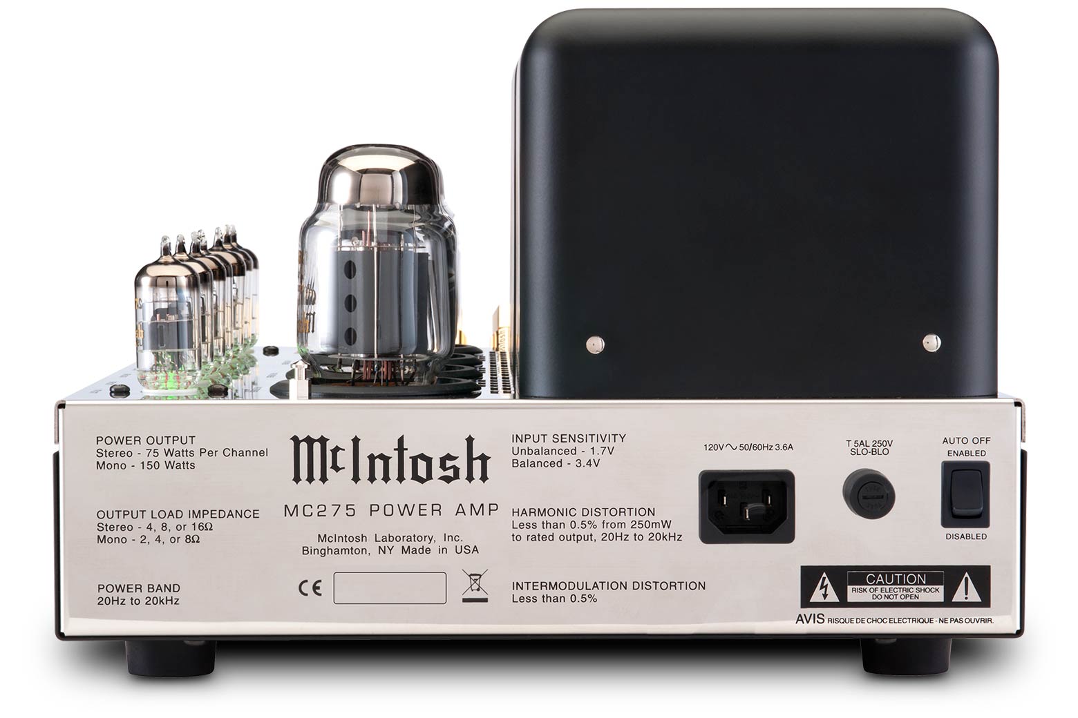
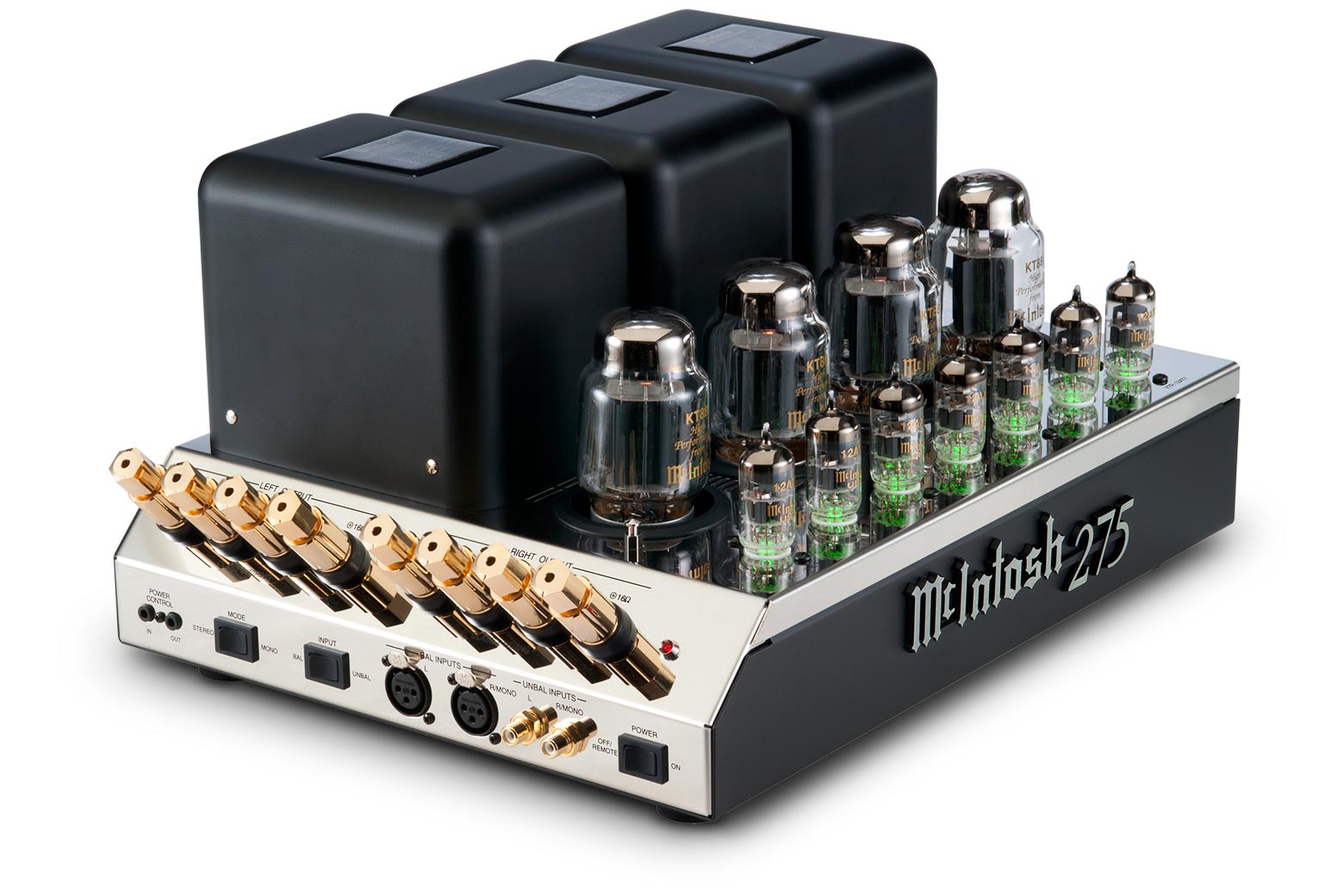
Official McIntosh product photography. Select any image for a larger view.
Choose your depth
Open only the parts you want to explore.
01 How a power tube amplifies a musical signalFundamentals
The incoming music signal is a control signal, not the source of the loudspeaker's power. It changes the voltage at the tube's control grid. That voltage varies the flow of current from the amplifier's power supply through the tube. A small grid-voltage change can therefore govern a much larger change in plate current.
The output signal is the controlled power-supply current carrying the same musical pattern at a useful power level. This distinction—control from the input, energy from the power supply—is the foundation for understanding every power amplifier.


02 What the output transformer must doConventional tube amplifier
Loudspeakers and power tubes require very different voltage, current, and impedance conditions. The output transformer provides the magnetic bridge between them. In a push-pull amplifier it also combines the two complementary halves of the musical waveform.
A conventional transformer must balance competing requirements. More primary inductance helps bass extension, while leakage inductance and winding capacitance can restrict high-frequency behavior. Imperfect coupling also complicates the use of corrective feedback. This transformer problem was the problem McIntosh set out to solve.


03 What Unity Coupling changesThe McIntosh architecture
The Unity Coupled Circuit uses separate but tightly related primary windings in the plate and cathode paths of the output tubes. McIntosh literature describes the paired primaries as bifilar wound—wound together so their magnetic behavior is very closely coupled.
Because the cathodes participate through their own winding, part of the output is returned locally in opposition to the tube's change. This degeneration helps linearize the output stage. At the same time, the close winding relationship reduces the leakage that would otherwise compromise bandwidth and stability.


04 Follow one musical cycle through the circuitSignal operation
A phase splitter drives the two sides of the push-pull output stage in opposite directions. On one half-cycle, one tube increases current while its partner decreases; on the next half-cycle, their roles reverse. Their magnetic contributions combine in the transformer secondary to reconstruct the complete loudspeaker waveform.
In the Unity Coupled arrangement, the plate and cathode windings act throughout that cycle. The cathode-derived local correction is immediate and confined to the output stage, while the transformer secondary presents the reconstructed signal to the selected loudspeaker connection.


05 Translate the engineering into amplifier behaviorWhy it matters
The architecture joins several ideas that reinforce one another: tightly coupled primaries, local cathode degeneration, plate-and-cathode participation, and transformer taps that match the output stage to supported loudspeaker loads.
McIntosh technical literature connects those choices with low distortion, flat response, wide power bandwidth, close control of the output stage, and cool-running output tubes. These are engineering objectives rather than a promise that every recording or loudspeaker will sound the same.

Origins and evolution
An engineering idea at the beginning of McIntosh.
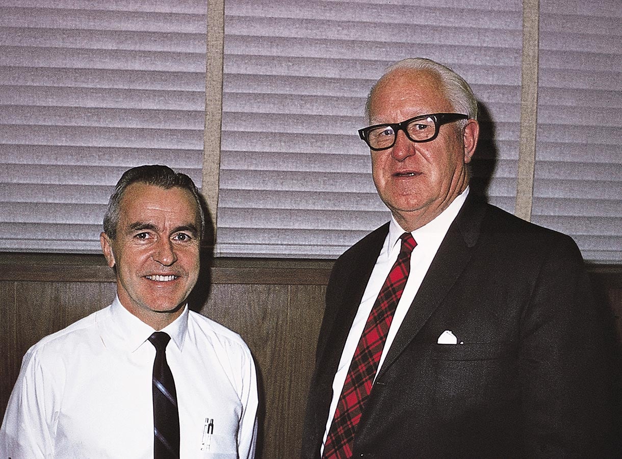
The Unity Coupled Circuit belongs to the founding story of McIntosh. Frank H. McIntosh was working to overcome the limitations of the high-power audio amplifiers of the period, and Gordon J. Gow became the key engineering collaborator who helped turn that work into a practical amplifier architecture. U.S. Patent 2,477,074 was filed on December 22, 1948 and granted on July 26, 1949, the year McIntosh Laboratory was founded.
The patent describes a push-pull amplifier with tightly coupled transformer windings arranged around the output tubes to pursue wider frequency response and lower distortion than conventional output stages of the era. The topology became a signature of selected McIntosh vacuum-tube power amplifiers. Later generations changed tubes, power levels, protection, controls, and connections, but retained the central plate-and-cathode relationship that makes the circuit recognizably Unity Coupled.
This history also explains why the technology remains relevant to the brand. It is not a decorative reference to McIntosh's past; it is an engineering idea from the company's beginning that continues to define how selected McIntosh tube amplifiers deliver power to loudspeakers.
People at the beginning: Frank H. McIntosh; Gordon J. Gow

The original drawings
From the 1949 circuit to Corderman’s later design
Frank H. McIntosh’s Wide-band amplifier coupling circuits, U.S. Patent 2,477,074, was granted on July 26, 1949.
Sidney A. Corderman’s later Amplifier patent, U.S. Patent 2,886,655, was granted on May 12, 1959. It builds on McIntosh’s earlier output-stage designs with developments in the driver, bias, and feedback circuits.
View Sidney Corderman’s 1959 patent drawing ↗
Original patent scans courtesy of Google Patents. Both images are hosted by Pearl Audio on Shopify.
Continue with the equipment
McIntosh models using Unity Coupling
Explore current Pearl Audio product pages, then arrange an audition to hear the amplifier in a carefully matched system.